
Cooka engineering · Application selection · Updated 24 October 2026
The short answer
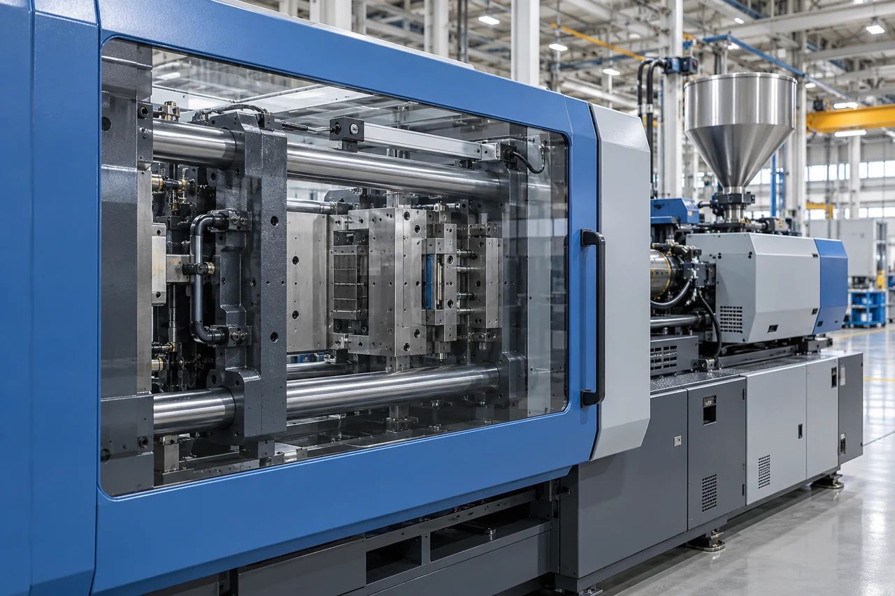
An injection moulding machine uses linear position sensors to tell the controller where the moving parts are, so it can repeat each shot accurately. Choose a sensor by specifying five things: the axis it measures, the useful stroke, how it mounts and couples, the signal the controller expects, and the machine environment. Cooka’s starting formats are the compact CLP25 (25 mm stroke) and the rod-style LEC displacement sensor.
Where the machine needs position feedback
- Clamp unit: mould open and close position, so the platen slows before contact and opens to the right stroke.
- Injection unit: screw position, which sets shot size, injection speed profile and switch-over to holding pressure.
- Ejector: ejector stroke for reliable part release.
- Nozzle or carriage: forward and back position of the injection unit.
Each axis has a different stroke and duty, so treat them as separate sensor selections.
1. Stroke and installation length
Measure the useful stroke on the machine, then the installation length available, including the sensor body beyond the stroke. A short axis may suit a compact sensor such as the CLP25; longer machine travel usually calls for a rod-style sensor such as the LEC, configured to the required travel.
2. Mounting and coupling
Most early failures on moulding machines come from mounting, not from the sensor itself. Keep the sensor parallel to the moving part, use a coupling or rod-end that tolerates small misalignment, and leave clearance through the whole movement. Send Cooka the mounting references and how the moving part connects to the sensor.
3. Signal and controller
Confirm what the machine controller expects: a resistive voltage-divider signal or a conditioned output, the supply voltage, and the connector. Ask for the resistance or output, connection and supply definition for the selected configuration rather than assuming one from a similar part.
4. Repeatability and dynamics
Shot-to-shot consistency depends on how repeatably the sensor reports the same position. Define the repeatability you need on the screw axis, the movement speed and the cycle rate, and agree how they will be checked during sample evaluation.
5. Machine environment
Moulding machines combine heat near the barrel, hydraulic oil, dust and continuous vibration. List the temperature at the mounting position, contamination and cable routing, and keep the sensor and cable away from heater bands where possible.
Compact or rod-style?
What to send Cooka
- Which axis the sensor measures.
- Useful stroke and available installation length.
- Mounting references and coupling method (a drawing is best).
- Controller signal, supply and connector.
- Temperature, oil, dust and vibration at the mounting point.
- Expected quantity and sample timing.
- MOQ
- From 10 pcs standard configurations
- Lead time
- 3–7 days stock items
- Samples
- Free qualified projects
- 3D model
- STEP on enquiry
FAQ
Where are linear position sensors used on injection moulding machines?
On the clamp unit (mould open and close), the injection screw (shot size and switch-over), the ejector and the nozzle or carriage.
Which Cooka sensors suit injection moulding machines?
The CLP25 compact linear position sensor (25 mm stroke) and the LEC rod-style displacement sensor, configured to the machine’s travel.
What causes early sensor failure on moulding machines?
Most early failures come from misalignment, side load and poor coupling. Mount the sensor parallel to the moving part and use a coupling that tolerates small misalignment.
What should I send for a quotation?
The axis, useful stroke, installation length, mounting and coupling, controller signal and supply, environment and expected quantity.
What is the MOQ and lead time for Cooka potentiometers?
The MOQ starts at 10 pieces for standard configurations and the lead time is 3–7 days for in-stock configurations. Free samples are available for qualified projects.