
Technical summary
Selected specifications, options and available reference drawings, compiled from the supplied CRS16 datasheet. Reference summary, 28 September 2026.
Download PDFProduct appearance and terminals vary by configuration.
A 16 mm carbon-element potentiometer for compact rotary controls, with shaft, bushing and rotation options.
| Resistance range | 200 Ω to 500 kΩ |
|---|---|
| Standard resistance tolerance | ±20% |
| Resistance taper | Linear |
| Linearity | ±2% in the electrical table; ordering codes span ±1.5% to ±3% |
| End resistance | 20 Ω maximum |
| Noise (C.R.V.) | 200 mV |
| Power rating | 0.25 W at 40 °C, derated to 0 W at 85 °C |
| Maximum input voltage | 50 VDC |
| Rotation options | A: 300° mechanical / 280° electrical; B: 360° / 340°; C: 360° / 320°. |
| Precision options | Linearity codes A ±1.5%, B ±2%, C ±2.5%, blank ±3%. Resistance tolerance ±10% or ±20%. |
| Mechanical angles | 180° / 300° / 312° / 360°, configuration dependent |
|---|---|
| No-load rotational life | 1,000,000 cycles; 2,000,000-cycle ordering option |
| Life-test acceptance | Total resistance change ≤ ±5% |
| Operating temperature | −30 to +85 °C |
| Storage temperature | −40 to +105 °C |
| Protection | IP65 |
| Operating torque | 40 gf·cm maximum |
| Shaft & bushing options | Flat, slotted or round shafts; 6.35 mm or 10 mm bushings; 20 mm or 25 mm FMS options. |
| Life options | S: 1 million cycles; P: 2 million cycles. |
Linearity and life depend on the order code. Continuous mechanical rotation does not imply 360° effective electrical travel.
Options are not automatically interchangeable. Confirm the complete order code, drawing revision and performance requirements in the quotation.
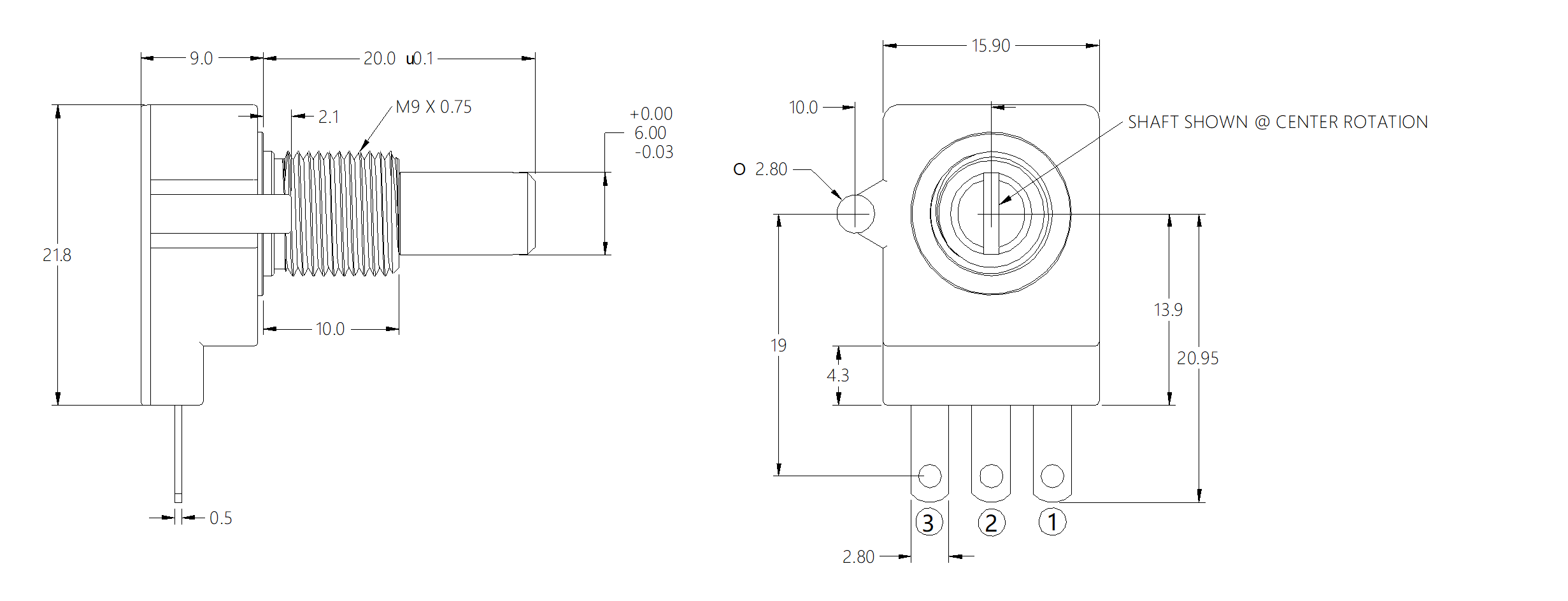
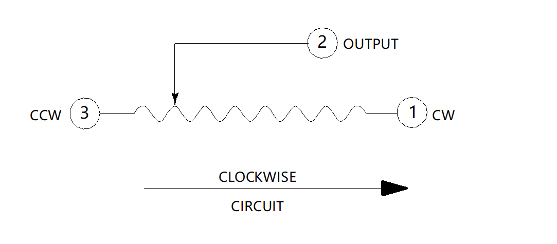
Reference circuit: terminal 2 is the output; terminal 1 is CW and terminal 3 is CCW. Match the terminal view to the assembly drawing.
Selected specifications, options and available reference drawings, compiled from the supplied CRS16 datasheet. Reference summary, 28 September 2026.
Download PDFRequest the controlled drawing, connector information and applicable test documents for your quoted part.
Request Part DocumentsSend the application, quantity and drawing. We will review the configuration with you.