
Stroke & mounting
Define the useful travel, mounting centres, coupling alignment and clearance through the full machine movement. Misalignment is a common cause of early wear.
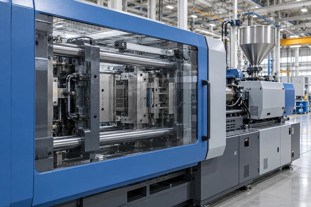
Injection moulding machines need reliable linear position feedback on the clamp unit, the injection stroke and other moving mechanisms. Cooka offers the CLP25 linear position sensor with a 25 mm stroke and the LEC rod-style displacement sensor as starting formats, configured to the travel and mounting of your machine.
Define the useful travel, mounting centres, coupling alignment and clearance through the full machine movement. Misalignment is a common cause of early wear.
Match the output to the machine controller and review response, repeatability and the cycle rate of the moulding process.
Specify temperature, vibration, oil and dust contamination and cable routing, and agree the evaluation conditions for the chosen configuration.
| Model | Type | Stroke | Construction | Electrical |
|---|---|---|---|---|
| CLP25 | Linear position sensor | 25 mm stroke | Alloy housing | Electrical characteristics confirmed per configuration |
| LEC | Rod-style displacement sensor | Travel specified per application | Rod-style format | Resistance or output, connection and supply confirmed per configuration |
Values are taken from the published series pages. Confirm the exact configuration, drawing revision and performance in the quotation.
Read the full guide: choosing a linear position sensor for an injection moulding machine
The CLP25 linear position sensor (25 mm stroke, alloy housing) and the LEC rod-style displacement sensor are Cooka’s starting formats for clamp and injection-stroke feedback.
Yes. Send the useful travel, installation length and mounting references; Cooka reviews the configuration against your machine drawing.
Stroke, installation length, mounting and coupling, controller interface and supply, operating environment and expected quantity.
The minimum order quantity starts at 10 pieces for standard configurations; custom configurations are quoted per project.
Lead time is 3–7 days for in-stock configurations.
Yes. Cooka provides free samples for qualified projects.
Send the model, drawing or application. Cooka engineers will review the configuration with you.