
Begin with the mechanism
Panel controls, control levers and rotary feedback assemblies place different demands on the same small component. Start by describing the motion: whether the shaft stops, whether it rotates continuously, and which part of that motion must produce a useful electrical signal. A mechanical angle and an effective electrical angle are different requirements.
Compare the available formats
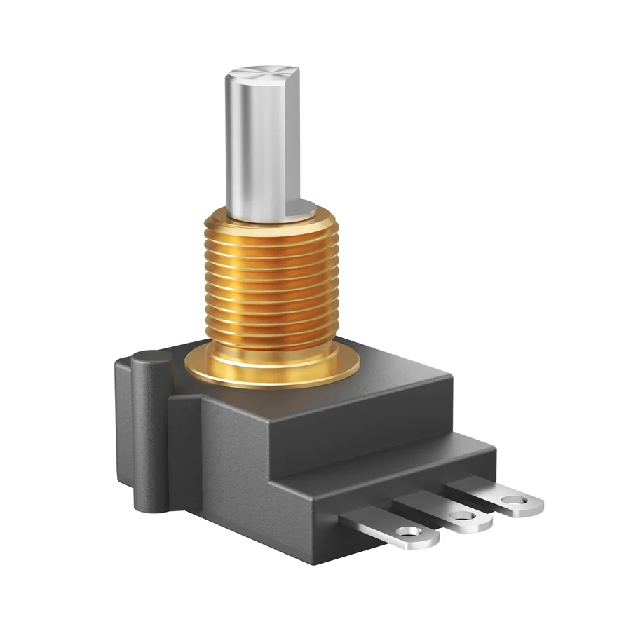
| CRS16 | 16 mm body; 200 Ω–500 kΩ resistance range; flat, slotted or round shaft options. The series datasheet lists IP65 and a standard 1 million no-load cycles. |
|---|---|
| SRS22 | 22 mm body; 1 / 2 / 5 / 10 kΩ standard resistance values. The detailed life table specifies 5 million no-load cycles with a special 10 million-cycle option. |
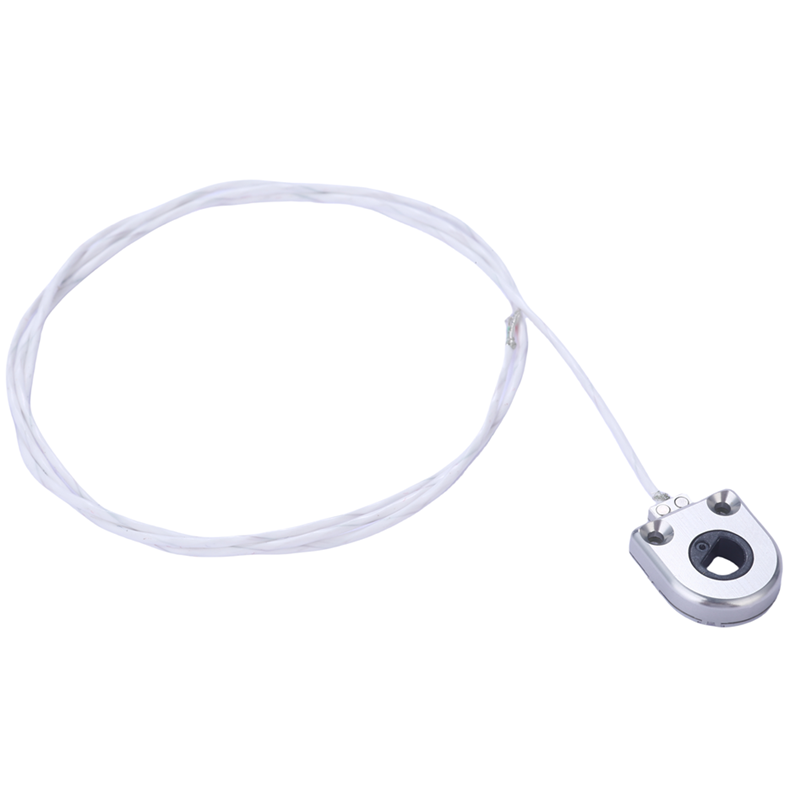
| HRS12 | Published series overview: 12 mm hollow-shaft format and 3.2 mm profile. Request the configuration drawing to confirm the bore and mounting arrangement. |
Check the interface before choosing the rating
Put the shaft or bore profile, mounting method, available depth and connector clearance on the same drawing. The CRS16 order information offers multiple bushing and shaft formats. The SRS22 construction codes also change the terminal arrangement, so matching the body diameter alone is not enough.
Match the signal to the useful motion
For CRS16, one documented angle option combines 300° mechanical rotation with 280° electrical travel. A 360° mechanical version can have 340° or 320° electrical travel. For SRS22, the selected angle code also defines the electrical response. Review the chosen curve and terminal view with the actual direction of motion.
Make the sample review specific
Check mounting fit, available travel, output direction and the electrical response in the assembly. Compare observed behaviour with the applicable drawing and specification. Datasheet life values are no-load tests; they do not predict the service life of a loaded mechanism without considering its operating conditions.
What to send Cooka
- A sketch or drawing of the shaft, mounting and surrounding space.
- Mechanical movement and the required electrical travel or signal.
- Resistance, supply and interface requirements already defined.
- Operating environment, sample quantity and expected production quantity.
These are selection examples based on series documentation, not a report of a completed customer installation.