
Separate control input from machine feedback
A manual fader gives an operator a physical control interface. A motor fader adds driven movement and introduces motor, connector and controller requirements. A displacement sensor is mounted to a mechanism to track its position. Similar-looking linear motion does not make these formats interchangeable.
Compare the documented starting points
| SVR01 manual fader | 45 / 60 / 100 mm travel; single or duplex construction; light or heavy operating feel; 5 / 10 kΩ standard resistance. |
|---|---|
| MSV02 / MSV05 motor faders | 60 / 100 mm travel. MSV05 offers FFC-1.0-10P or PH-7P connector options. Confirm the motor supply and drive requirements separately. |
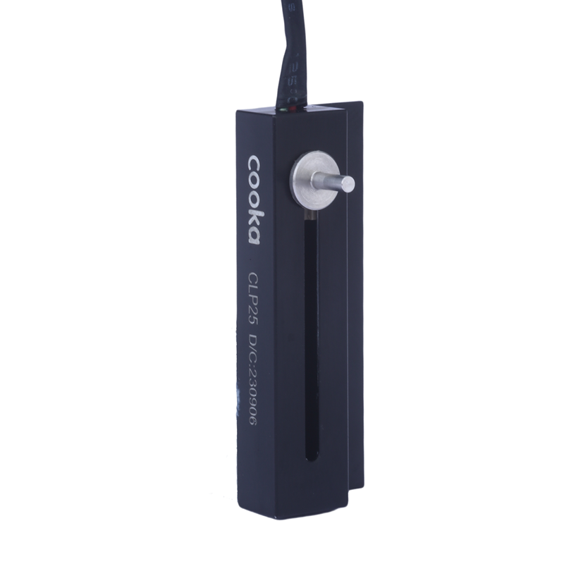
| CLP25 displacement sensor | 25 mm stroke in the published series overview. Review the linkage, mounting and controlled drawing for the exact configuration. |
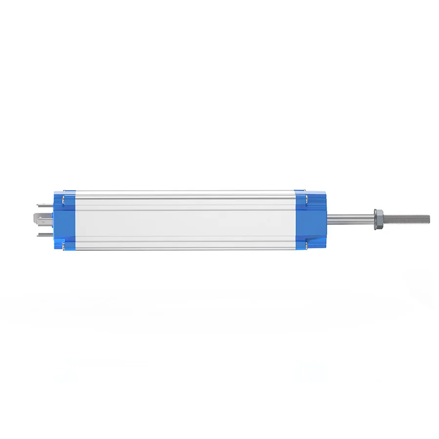
| LEC displacement format | The product imagery shows the body, moving rod and connector. Send the required stroke and installation dimensions to identify an appropriate configuration. |
Travel is only the first dimension
For a fader, include the panel opening, mounting holes, lever height and the space beneath the panel. For a rod-style sensor, include the moving linkage, mounting references, cable clearance and alignment through the full stroke. The overall housing length is not the same as the measurement travel.
Confirm the electrical interface
SVR01 includes taper and track-configuration options. MSV02 and MSV05 require a separate review of motor integration. The 200 VDC maximum element input voltage in the motor-fader datasheets must not be used as a motor supply rating. The motor operating voltage is not specified in those series documents.
Compare life values in context
The detailed MSV02 table lists 1 million no-load cycles. MSV05 lists 2 million cycles, while its L order code is 1 million cycles. SVR01 lists 1 million no-load cycles with a different resistance-change acceptance criterion. Use the configuration and test definition together rather than ranking parts by cycle count alone.
Build an actionable enquiry
- State whether the part is an operator control or a feedback sensor.
- Include required travel, body space, mounting and linkage details.
- Specify manual or motor-driven movement and the control interface.
- Share the application environment, duty and sample requirements.
This is an application selection guide, not evidence of an installed customer project.