
Start with the controlled interface
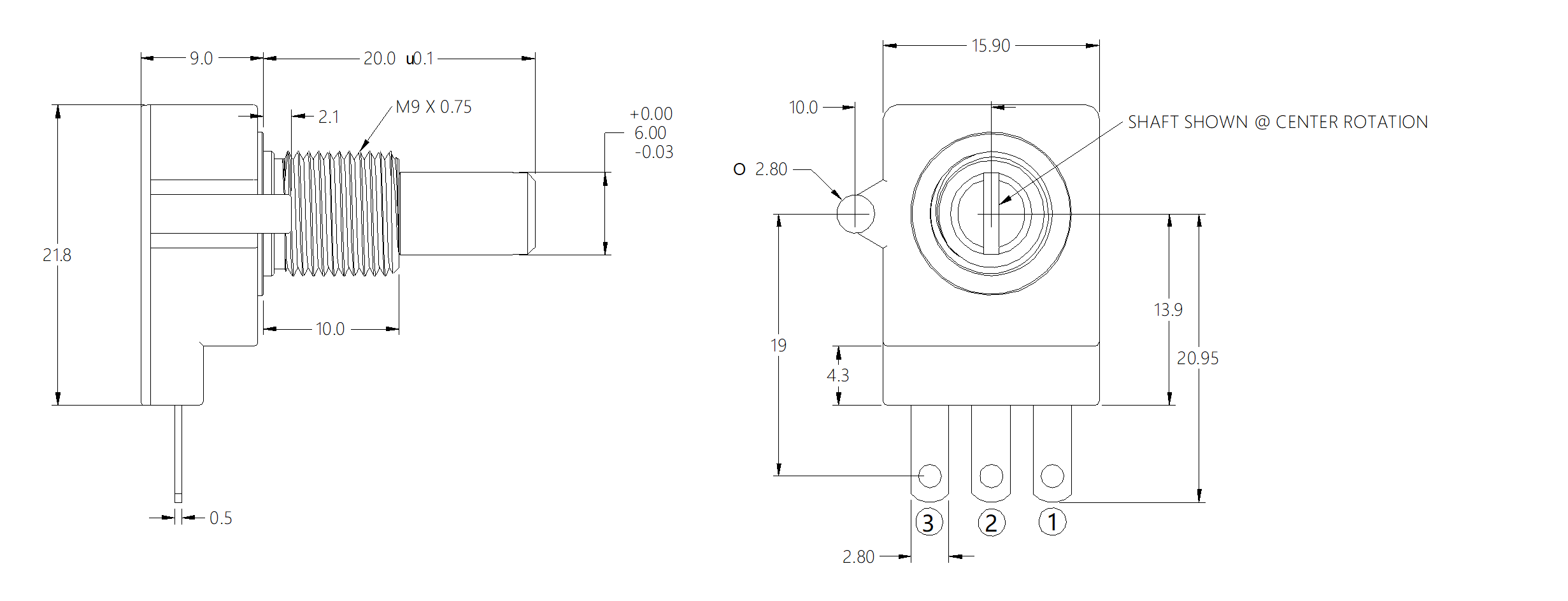
Read the mounting drawing from the assembly outward. Identify the panel face, mounting datum, bushing or shaft centreline, available clearance and the direction in which the control moves. A 22 mm body label is a useful family reference, but the shaft length, bushing, fixing features and terminal side determine whether the part can actually fit. Keep the drawing revision beside the model and order code used in the review.
Compare two 22 mm references
SRS22 and RVR22 share a nominal body diameter, yet their documented construction choices are different. Use the comparison below to decide what the drawing must show for your assembly.
| Drawing question | SRS22 | RVR22 |
|---|---|---|
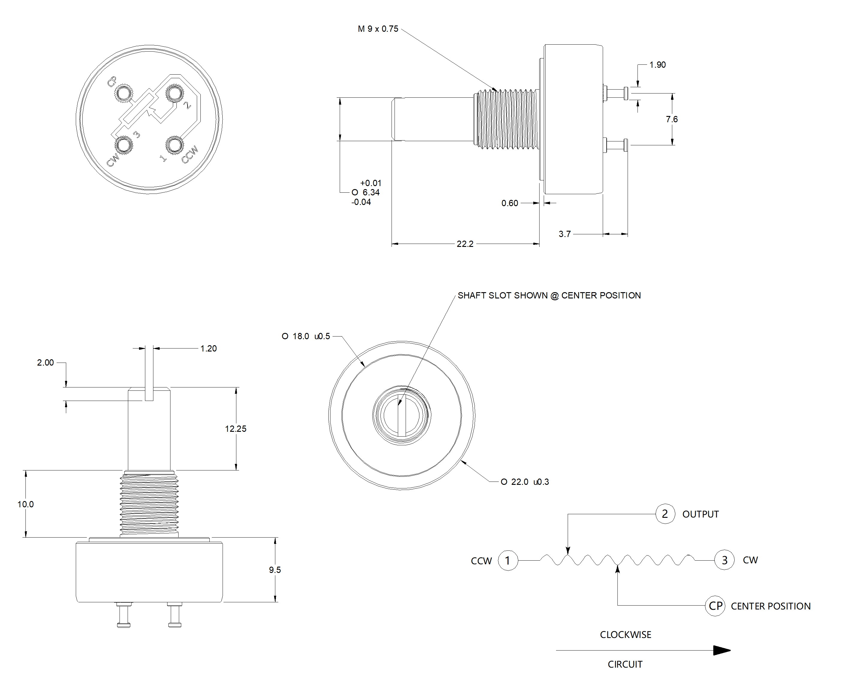
| Construction and interface | S, SL, M, T and V constructions; the source circuits show three terminals for SL and V, and four for S, M and T. | 22 mm carbon-element series with shaft material choices including brass, SUS303 stainless steel and aluminium. |
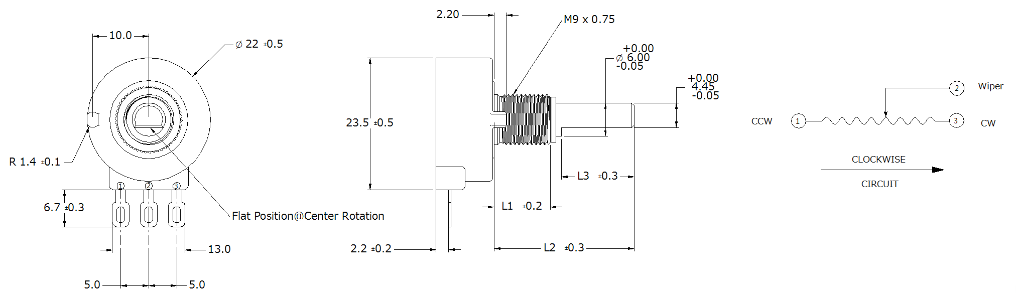
| Shaft, bushing and fit | Match the construction drawing and its terminal view to the selected mounting envelope. | Flat, slotted or round shaft; 6.35 mm or 10 mm bushing; 20 mm or 25 mm FMS options. |
| Travel reference | 360° mechanical rotation; the angle code sets the effective electrical travel, such as 90° × 2, 280° or 340° codes. | Mechanical angle is configuration dependent: 180° / 300° / 312° / 360°, with the electrical angle code matched to it. |
| Electrical and service boundary | Standard tolerance is ±10%; linearity is selectable from ±0.25% to ±2% by code. Supplied protection is IP67; confirm the quoted type. | Standard tolerance is ±20%; the detailed table lists ±3% linearity. Life codes are E 300,000, S 1,000,000 or P 3,000,000 cycles. |
These are documented starting points. A material or option capability belongs to the applicable order code; it is not automatically a whole-assembly rating.
Read four dimensions before ordering
- Mounting datum: verify panel thickness, fixing holes, bushing length and the reference face used for every critical dimension.
- Control interface: check shaft profile, diameter, length, flat or slot orientation and the clearance needed for the knob or coupling.
- Movement: separate mechanical stop angle from useful electrical travel. Do not infer the angle code from the body drawing alone.
- Connection: identify terminal numbering, output direction and the circuit shown for the exact construction. Wiring is part of the interface review.
Separate standard values from options
Use the standard resistance and tolerance only as the baseline for the quotation. For example, RVR22 lists 200 Ω, 1 kΩ, 2 kΩ, 5 kΩ and 10 kΩ as standard values, while shaft material, bushing, angle, linearity and life are configuration choices. SRS22 likewise needs a construction and angle code before its circuit can be released. If a drawing shows one variant, do not transfer its terminal layout or envelope to another variant without the matching controlled sheet.
Review the drawing and circuit together
The SRS22 product page links its construction drawings and explains how terminal 2 is used in the reference circuits. The RVR22 product page links the mounting reference and lists its shaft and bushing choices. Open the drawings below, then compare the selected interface with the surrounding assembly.
Close the open points
- Mark the fixed mounting dimensions and the tolerances that the assembly can accept.
- Record the model, construction, shaft or bushing code, angle and terminal arrangement.
- Confirm clearance at the mechanical stop and the actual control coupling.
- Request the controlled drawing for any variant that is not represented by the reference sheet.
When the drawing or interface is incomplete, use the SRS22 drawing request or the RVR22 drawing request with the panel constraints and open dimensions.