Start with the mechanism
Describe what moves, what the potentiometer must control or measure, and how much room the assembly provides. A body diameter by itself is not a complete selection: shaft or bushing fit, effective electrical travel, output direction and expected duty all affect the usable part. State the fixed dimensions first, then identify preferences that can be reviewed with Cooka.
Compare a documented pair
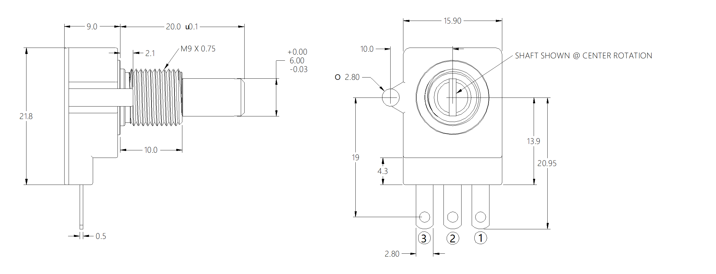
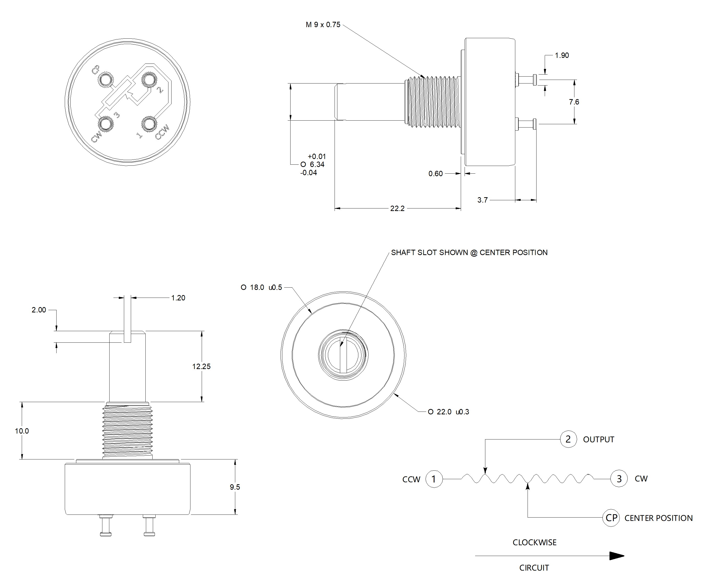
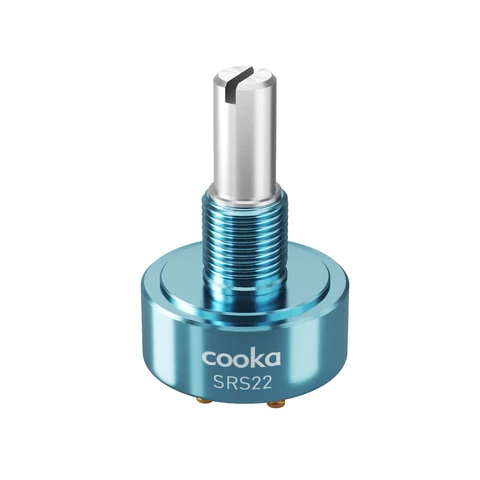
CRS16 and SRS22 are useful starting points for different envelopes. The table separates standard values from order-code choices so a headline figure is not mistaken for the complete specification.
| Selection point | CRS16 | SRS22 |
|---|---|---|
| Body and resistance | 16 mm body; 200 Ω–500 kΩ resistance range. | 22 mm body; 1 / 2 / 5 / 10 kΩ standard values. |
| Standard electrical starting point | Linear, ±20% standard tolerance; the detailed electrical table lists ±2% linearity. | Linear, ±10% standard tolerance; linearity choices include A ±1%, B ±1.5%, C ±2%, S ±0.5% and P ±0.25%. |
| Travel and life | 180° / 300° / 312° / 360° mechanical angles, code dependent; 1,000,000 no-load cycles, with a P 2,000,000-cycle option. | 360° mechanical rotation with the angle code setting effective electrical travel; 5,000,000 no-load cycles, with a special 10,000,000-cycle option. |
| Environment and protection | −30 to +85 °C operating; IP65. | −40 to +105 °C operating; IP67 in the series datasheet, subject to the exact configuration. |
The values above are series-level reference points. Tolerance, linearity, life and protection must be checked against the quoted configuration.
Read the options as a set
For CRS16, shaft shape, bushing size and rotation code are mechanical decisions made together: the documented choices include flat, slotted or round shafts, 6.35 mm or 10 mm bushings, and 180° to 360° mechanical angles. For SRS22, select the construction before wiring. S, SL, M, T and V types do not share the same terminal arrangement: SL and V are shown with three terminals, while S, M and T use four. The reference circuits identify terminal 2 as the output; the exact CW, CCW and optional CP connections depend on the type.
Run the selection checklist
- Record the body envelope, mounting method, shaft or bushing interface and panel clearance.
- Choose resistance, taper, tolerance and the required effective electrical angle.
- State the operating temperature, protection expectation and no-load cycle target separately.
- Identify the output terminal, rotation direction and connector or PCB constraints.
- Link the product page, technical summary and drawing revision used for the design review.
- Mark every open point for sample evaluation instead of treating an unconfirmed option as standard.
Use the source documents before release
Open the CRS16 product page and SRS22 product page for their configuration notes, then keep the matching CRS16 summary or SRS22 summary with the drawing. If the envelope, angle or terminal arrangement is not clear, use the document request route with the model and open question.