
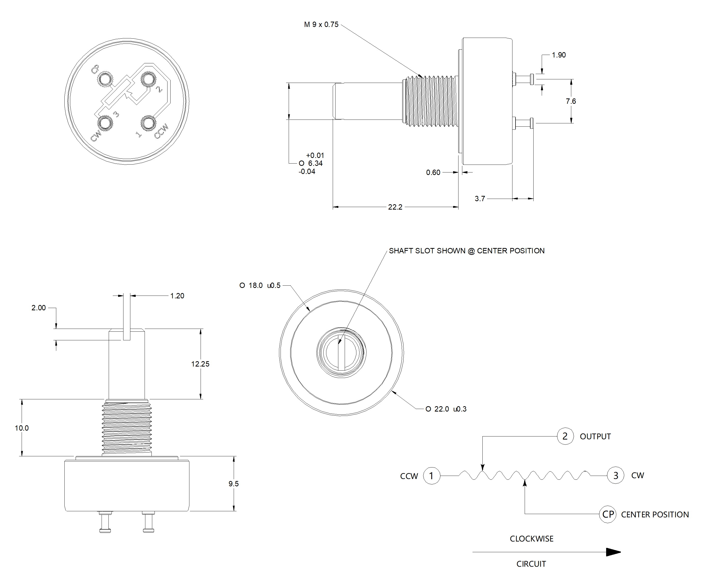
Start with model, code and revision
When a datasheet arrives, record the model name, order code, document title and revision before copying any value into a design record. A series can contain different travel lengths, lever styles, connectors or tracks. Keep the source drawing and the electrical table together, and write down which fields are standard, which are options and which still need confirmation.
Two examples show why the code matters
MSV02 and SVR01 both suit slide-control reviews, but they describe different mechanisms and different document questions. The table is a comparison aid, not a substitute for the exact controlled file.
| Document field | MSV02 motor-actuated slide | SVR01 manual slide |
|---|---|---|
| Travel and construction | 60 mm or 100 mm travel; T or TL lever construction in the source drawings. | 45 mm, 60 mm or 100 mm travel; single or duplex track; T08, T10, L10 or H15 lever options. |
| Resistance and tolerance | 5 kΩ or 10 kΩ; ±20% standard tolerance, with A ±10% or B ±20% order options. | 5 kΩ or 10 kΩ; ±20% standard tolerance, with ±10% or ±20% order options. |
| Linearity and life | ±2.5% maximum in the detailed table; A ±1% and B ±1.5% precision options; 1,000,000 no-load cycles. | ±3% maximum; 1,000,000 no-load cycles; life acceptance is total resistance change ≤ ±20%. |
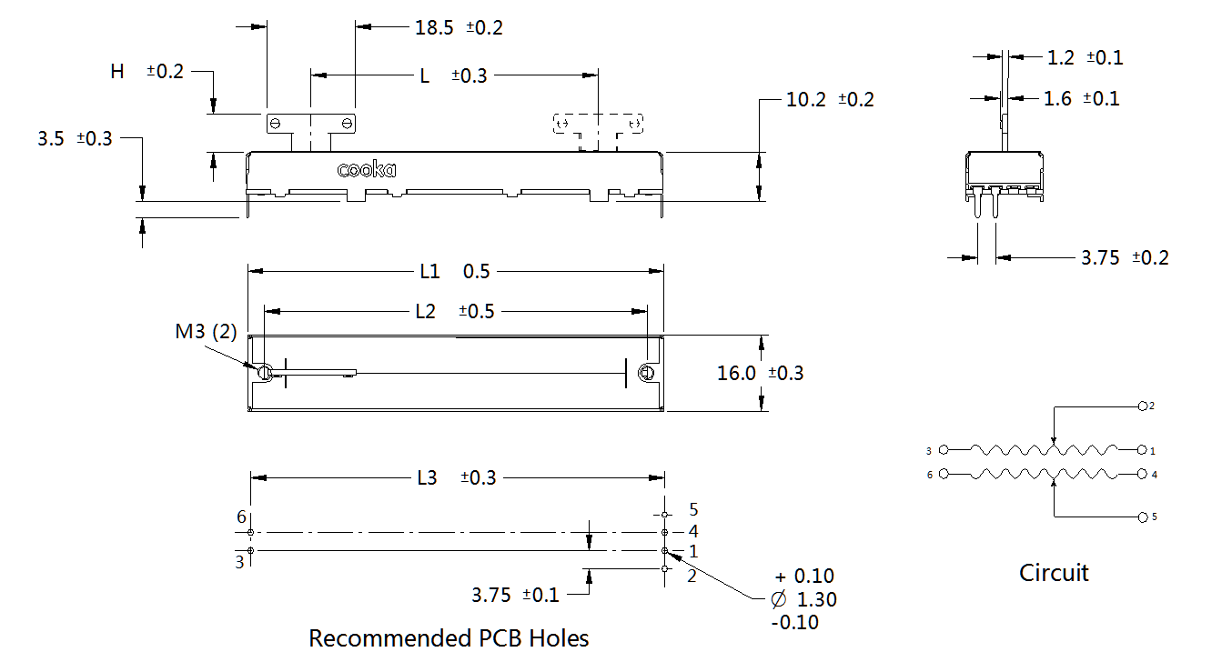
| Connection and boundary | The reference circuit includes motor terminals, resistive track and touch sense. 200 VDC is the element input limit, not a motor supply rating. | Single-track versions omit drawing holes 4, 5 and 6. The supplied specification lists 250 VDC maximum input; confirm the PCB footprint and connection. |
The detailed electrical values and the selectable codes must be read as one configuration. A standard resistance value does not make every travel, connector or life option standard.
Build a controlled document pack
- Exact identity: keep the model, complete order code, travel and construction or track selection in the review header.
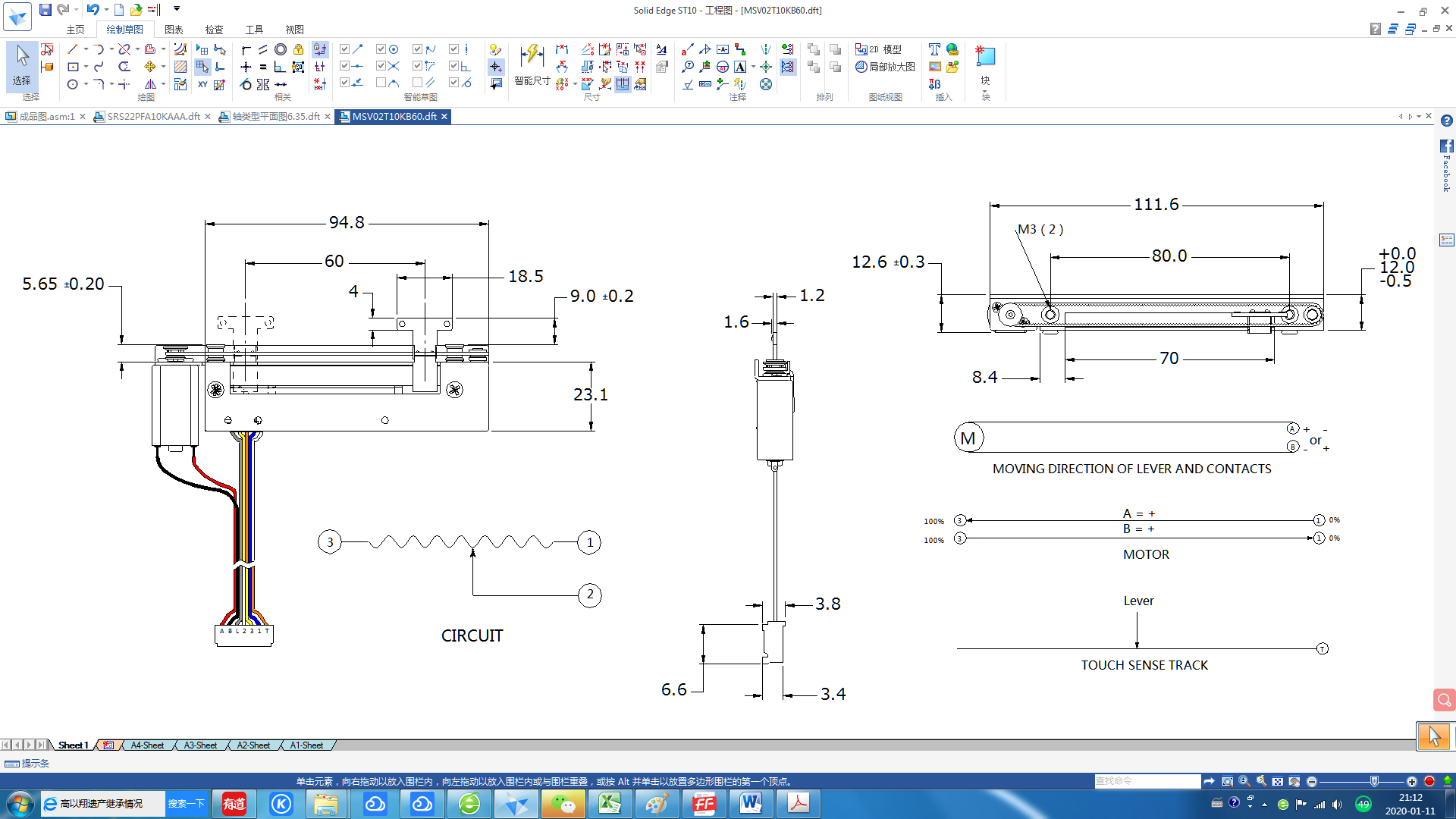
- Mechanical evidence: attach the drawing that matches the lever, travel and mounting pattern. Do not apply an MSV02 reference drawing to another motor-fader variant.
- Electrical evidence: record resistance, tolerance, taper, linearity and end resistance from the same revision.
- Connection evidence: retain the connector, pinout and circuit. For a motorized part, request motor supply and driver information separately when it is not specified.
- Scope and open points: label no-load life, temperature and input limits as datasheet conditions, then list what still needs sample or project confirmation.
Check scope and test conditions
Cycle-life values on these pages are no-load specifications, not lot-specific test reports. The MSV02 element input limit must not be reused as its motor supply. Likewise, the SVR01 single-track drawing changes the mounting-hole interpretation. Preserve those boundaries in the document pack so a material capability or a reference condition is not presented as a complete assembly guarantee.
Review the matching drawings
The MSV02 product page links the T and TL reference drawings, while the SVR01 product page shows the single or duplex mounting and circuit references. Keep the relevant image, specification table and open questions with the part record.
Request the missing revision
Use the MSV02 technical summary or SVR01 technical summary as a review aid, then request the controlled file when the ordered variant is not fully represented. The MSV02 document request and SVR01 document request can carry the model, travel, connector and open questions into the next review.